
Made with in India
Made with in India
This post is a part of a series i plan to write periodically to document my exploits with CNC machines and other stuff i have built! This post is about a stepper system tester i built a while back.
Stepper motors are quite widely used for CNCs/3D Printers or other Electromechanical hacks like the polar plotter etc. ! There is as always a constant need to run the motor to check whether its aligned properly or not? Does the flex coupling has any issues? Is the driver dead or alive and the best one- whether the current setting is fine to generate enough torque to hold or move the lead screw/Belt.
Pestered by the same above questions i wanted to build my own driver/motor tester overnight and it 'must' be built ACAP (As cheap as possible) :D ! I stumbled open this awesome project that i saw on Hack-A-Day.
It uses an ATiny AVR microcontroller which I did'nt have and the least capable one i had was the MSP430G2230 which came in a SOIC pkg a bit difficult to go on the perfboard and my laziness propelled me away from etching a board for accommodating the same (I now feel the need though). I thought of building a microcontroller-less one as most modern stepper drivers like the ones from Pololu need just two signal i.e STEP and DIR.
A pulse on step pin will initiate a step to the internal indexer that handles what coil has to be energized based on the sequence and micro-stepping settings, while the DIR is a level signal whose level decides whether the internal indexer of the driver counts up or down!
So, only two inputs i.e Pulsed input for STEP and level input for DIR. This can be achieved using the 555 timer in the astable mode. The Output of 555 i.e pin 3 will go into the step pin and the DIR pin is pulled up using a resistor and it is also connected to ground via switch.
This gets the job done! We can also have a POT to vary the frequency since some motors don't respond to faster pulses due to rotor inertia.The driver i am using is based on DRV8825 from TI. It is slightly wider than the polulu one. (You might call me a TI fan boy). I designed it myself based on reference designs by TI and had the PCBs made by SeeedStudio's Fusion PCB Service. It took about 30 odd days to reach. The driver is two layer in-contrast the Pololu ones are 4 layer. I had to widen the PCB to provide enough dissipating area for the inbuilt heatsink on the the HTSSOP pkg of the DRV8825. Also the SMD resistor cousins of those lower value resistors were not available here in Delhi, so had to go with through hole ones. Ditto for the POT !
With the Tester designing almost final , I grabbed a piece of perfboard since, i didnt have the time to etch the board.
The circuit is as follows:

It has two power inputs 12v, 5v and a common ground, all of which are sourced from an ATX! The circuit itself is pretty simple.
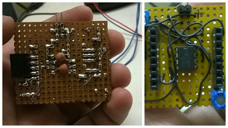
The final build on a perfboard is shown below.


I chose to use a SMD 0603 10K resistor between pin 8 and 7 to reduce the space and connected 104 (0.1uF) Ceramic caps as shown. The switch is a 10xx and the capacitor is required at the input of stepper driver to reduce supply dips when it draws current. I have used female headers for the motor since most motors come with a connector that can be easily wired up with a single strand wire. I used the Power Terminal connectors for the main 12V Driver supply as the driver is rated for 2.5A which is too high for the usual jumper cables !
TIP: If you are using the non-tinned/less tinned headers that have been lying around in the component box for a while, make sure to rub the connectors using sandpaper to remove corrosion residue on the contacts else it might seem soldered but it wont actually be soldered. Also you may use some extra flux.
Video:
Cheers !
Rohit Gupta