
Made with in India
Made with in India
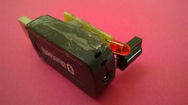
I recently ordered this Bluetooth to Aux Adapter from eBay to put an end to tiny wires running down from my phone to the USB (powered) speakers. The aux (3.5mm) that came with my USB Speakers is too small to offer scope of considerable activity like picking phone up for texting or checking mail and Changing Songs. Its more like getting chained to the speakers. Woof !!
After ordering from China it comes home in about 30-35 days, not their fault,Its we who choose the Free Shipping fellas !
It worked as advertised. But the range was hardly 15feet LOS and in a maze like house i live in , it would hardly go through the walls. So, the Wireless problem was partly solved but still not very convenient as i still need to be near the phone to change songs. Unlike the conventional problem solving mantra , “Think out of the box !” my answer was inside the box.
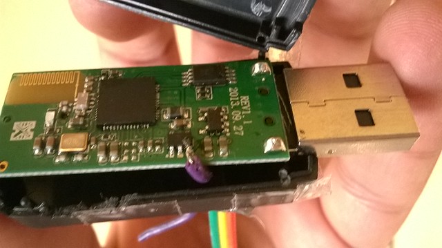
It was take-apart time. Opening the flimsy but nicely designed plastic case with an overgrown fingernail i found these inviting Test Pads :
Clearly my job was half done: we knew the Protocol (UART) and the points. I didnt knew the Chip i was talking too (the manufacturer had wiped off the name ) , the baud rate or any commands that it will work with (like the AT Commands).
Google helps ! I found this nice forum post detailing the adapter. Bingo its the OVC3860 Chip. And here are the commands.
Basically all commands are in a AT#CMD[cr][lf] Format. The “CMD” for a particular action is mentioned on the sheet above. Thats pretty much all the code you need to control it.
The baud rate was not known, so i tried a couple of them like 9600 etc and found that the particular one that i have is a ‘115600’ one. This setting seems to be stored in the EEPROM on the adapter. As this post suggests you can even change the device name by playing with the EEPROM ( Will Try later)!
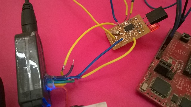
So, it was time to wire the MSP430 Launchpad to the adapter and get things talking. This is the first test video i made!
Tested it for a few days ! I could now control my phone’s audio tracks from the IR Remote. Now it was time to make it look nice. Convert the idea from a bunch of wires to a PCB.
I wanted it to 3D Print a new case but couldn’t so, made a PCB that would sit on the Top of the adapter and command it. I was lucky to have a 3.3V Regulator inside the adapter so, an extra regulator was not required. For the project i used the MSP430G2553 microcontroller in a TSSOP20 package running @ 16Mhz and programmed using Energia! I added some standard condiments like a LED and an extra SMD tactile switch to further expand capabilities.
The connections are simple.
The IR receiver is connected pin 11 and the adapter is interfaced over UART with crossed Rx and Tx lines. I have used decoupling caps on the controller and the receiver. Pull ups for the switch and RESET Line. Current limiting resistors for the LED. A solder jumper for Vcc just in case I dont turn ON the adapter while programming the MCU (You never know), and some programming pads !
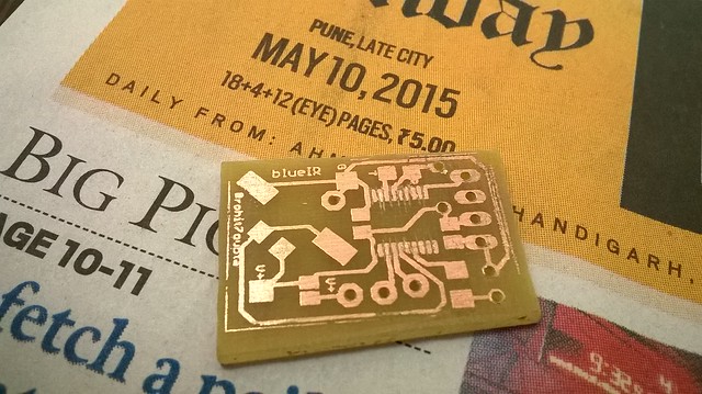
After designing the board it was time for the best part : Etching
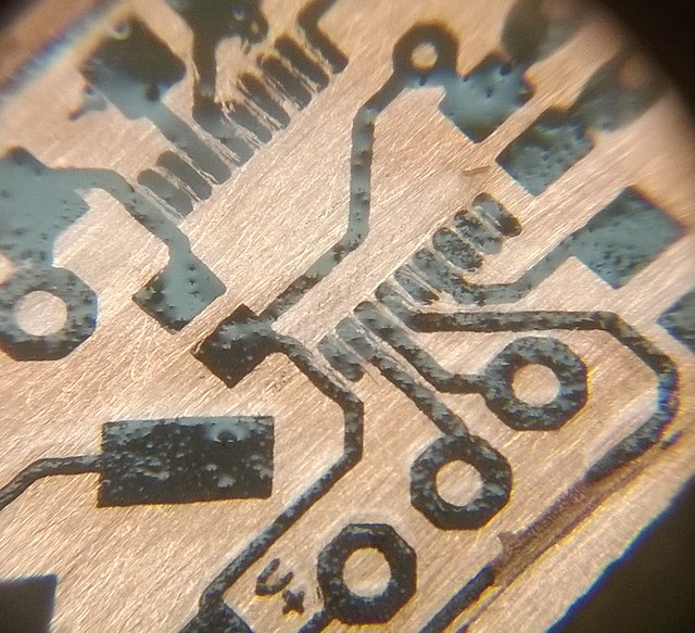
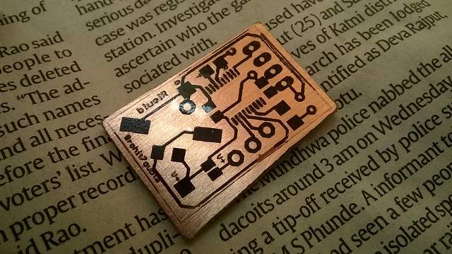
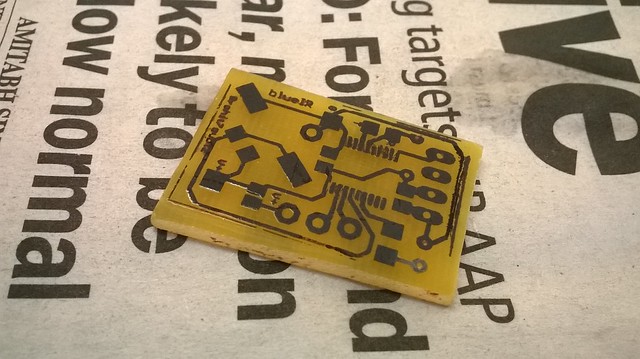
Here are the chronologically arranged pictures of PCB Etching using Toner Transfer Method :
Making sure the TSSOP Pads got nicely transferred. Clicked using MACROCase .
All set for the bath.
Rough times to follow.
After some sanding.
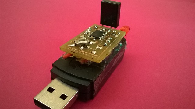
Flashing the code after soldering.
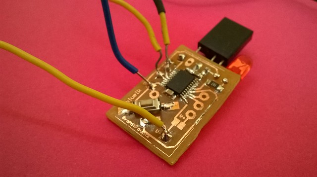
Testing.
Ta Da !!
Check out the video for the project in action:
Interested in building one? Grab the code here:
Cheers,
Rohit