
Made with in India
Made with in India
One fine day while i was rummaging through the part bin, I found an old project that probably was never completed ! FM Radio ! I tried to make one when i was in 7th grade, waiting at the counter of a dingy electronics repair shop for anyone to pay attention to the parts list gathered over the internet ( Dial up days ! ).
At that time, i just jotted down all i could from the internet and went straight to the repair guy expecting some help. It never did work and i soon lost interest but it remained until recently when i was skimming ebay to get some stuff and i saw ‘TEA5767 FM Receiver’ module selling for 0.99 $ . Cheap is attractive specially in DIY world and the rest was involuntary . After 20 days the module was with me.
TEA5767 is a digital FM Receiver chip from NXP/Phillips that can be commanded over I2C to tune to various frequencies easily.
But alas ! The one i got never matched with any pictures online ! Where was the missing “crystal” responsible for all the PLL stuff? Where are all the other pins ? That was frustrating. Thanks to the cryptic words written on the silkscreen “TT-502X” i was able to find out that only one person except me happen to have posted about this and he apparently has documented it in a schematic! Thanks to Dilshan, an amazing maker himself, I was able to get this done.
It turns out that the module is actually used in some Samsung Products and requires a generic watch crystal.
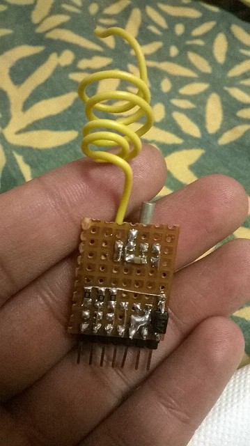
The connections are similar to what Dilshan mentions it in his post. I added a diode (Reverse Polarity. Ouch!) and a decoupling cap. And after a bit of work with the solder iron i was able to make my own FM Receiver Module.
Next step? Let others know about it… :D
FYI that pigtail type antenna was useless ! I needed a 81cm long wire for (Wavelength/4) law to work for 87.5 Mhz.
After doing the same! A commander was needed. Chose my workhorse, the MSP430 Launchpad for the extra switch they have on it that helps me change channels and doing that on arduino pro mini would require some breadboarding i was too lazy to try.
The code is pretty easy and shown below. It was coded using Energia IDE.
Based on the datasheet the I2C address of the device is 0x60 and we begin wire transmission using the wire library. Then we send the upper byte and lower byte of the frequency we wish to tune to based on the formula mentioned in to code and also on datasheet page 30 that depends on what clock you are using and whether you are using High side or low side injection. Since, we are using high side injection (Reason : Not known. Please share if you happen to know.) for superhetrodyne Receiver we used the formula mentioned in the code.
The other data bytes i.e. 0xB0 and 0x10 are for setting the chip for enabling stereo ,disabling mute, use the watch crystal , pull some programmable pins low, enable High side injection etc. Check the page 14 Of Datasheet for more info.
I made an array that has the channels available here in Pune and on the press of a button the global variable frequency is updated with the latest value and the function is called to set it inside the TEA5767 and Bam! It works !
If you need to check for signal quality and other things you can check out my github repo here .
Here’s me explaining the whole setup in detail !
Cheers,
Rohit