
Made with in India
Made with in India
Buzz..Buzzzz..buzzzzzzzz .. That is how a lone mosquito irritates you in the middle of the night trying to convince you that his lullaby is helpful. Insignificant or not, But truly that is the underlying inspiration for this project. The Mosquito repellents have this obnoxious smell that I would not like to sleep in and these loner mosquitoes who just piss me off by buzzing in the ear, you have to choose a lesser evil. Obviously, I turned ON the repellent and in a while it goes off but the smell starts building up and I am too lazy to turn it back OFF, leaving the warmed blanket on a chilly Delhi December Night. The nocturnal dilemma .
So, why not just use a remote to turn it back off and maybe add some other things like Reading Light control, Mood Lighting?
Interesting !!
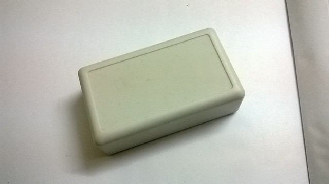
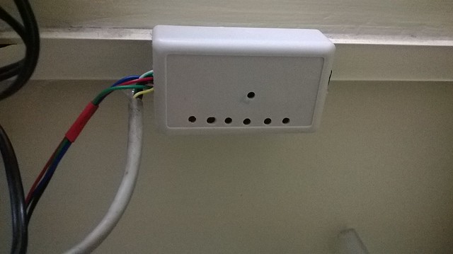
Having the above in mind I thought of building my own Room Automation and Mood Lighting controller and for this time make it look good and “no mess visible”. I had bought some nice overpriced project enclosures a while back and the bigger one of them would be perfect for the project.
So, the plan was :
Use the old Sony Remote and with it try simply turn ON/OFF some relays for the light sockets and also dabble with a RGB LED strip to give the room a different tint at night. The system should be able to tell if a wrong action has been taken by itself. Above all it should look good (on the wall).
For the recipe, the main ingredient is MSP430 as I was able to get it in a desired TSSOP package from TI itself (The local sellers don’t seem to like SMDs), Its easy to play with thanks to Energia and best of all - Low Power .
I chose to use MSP430G2553 as i already had the chip in DIP to prototype with.
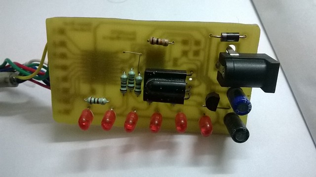
For driving the relays and the RGB LED strip ( a small part of the bigger strip with actually just 12 LEDs ) , I used ULN2803 , the octa darlington chip. And Yes ! I didnt use opto isolation for the relays.
For demodulating the 38kHz IR Pulse train, I used a locally available TSOP1738 IR Receiver and for regulating power to the MSP430 I used LP2950-3.3V, a TO92 packaged 100mA LDO .
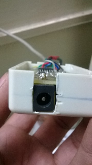
Next, i needed some LEDs to tell which load is ON/OFF and a DC jack to mate the final module with my wall wart.
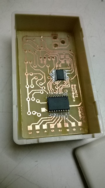
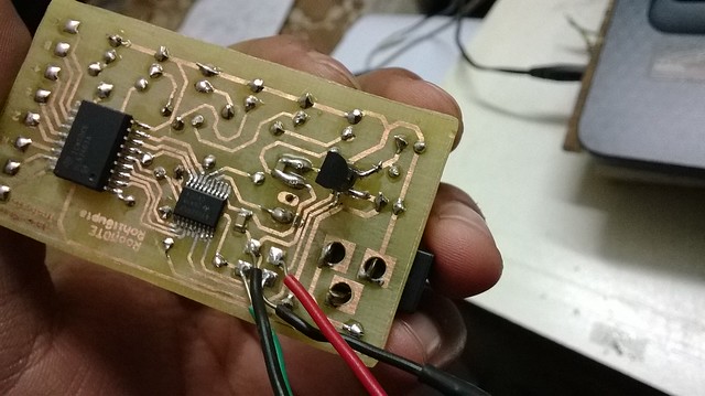
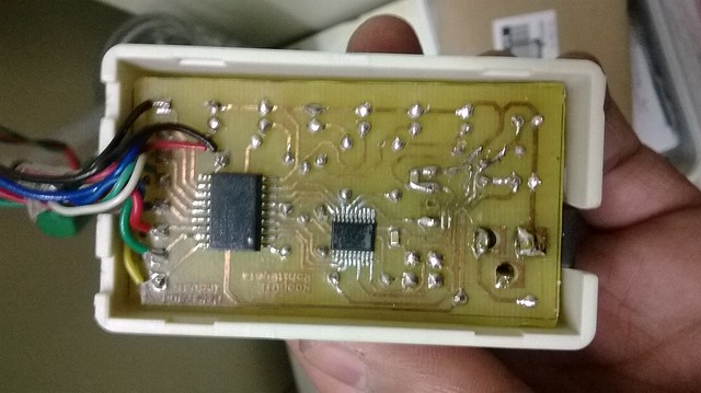
That’s pretty much the circuit part. Once, i had all the components on my table. I designed a small PCB to fit the box and house all the components and a separate Relay board for the Sockets ! Next after Toner Transfer and some etching in my OpenAgitator I got this sparkling PCB .
Some soldering !
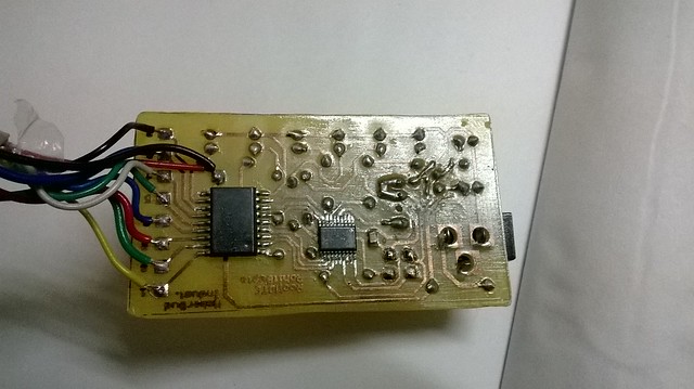
and some Brain Implant ( aka Code Download )
The Code :
Then modifying the nice little box to suit the PCB (That moment when you say, “If only i had a 3D Printer” )
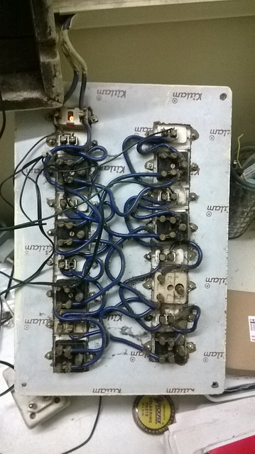
Next, made amends for the switch board to be compatible with the project. Basically, just added wires in parallel to the switches. Did somebody say Manual Over-ride ?
The wiring mess inside the switch-board.
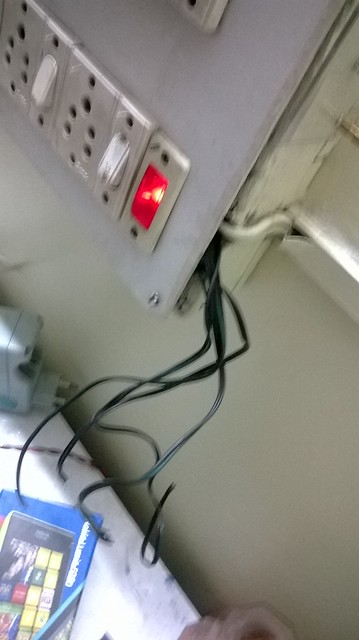
All cleared up !
After that, i simply wired the wires (!) to the relay board ( See the Video below ) and powered it up.
Now with a press of the button, Its all done ! I already feel so lazy!
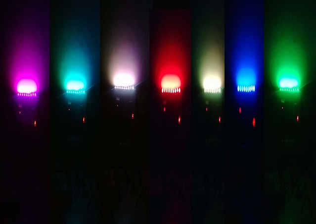
And yes here are the colors !
Dont forget to watch the video below and if you have something to say, Please Comment Down here!
Cheers,
Rohit